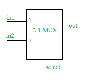
Requisito previo: multiplexores en lógica digital
. Problema:
diseño de un MUX 2: 1 utilizando el lenguaje de descripción de hardware Verilog junto con Testbench.
Conceptos:
Un multiplexor es un tipo combinacional de circuitos digitales que se utilizan para transferir una de las líneas de entrada disponibles a la salida única y, qué entrada debe transferirse a la salida se decidirá por el estado (0 lógico o 1 lógico). ) de la señal de línea seleccionada. El multiplexor 2:1 tiene dos entradas, una línea de selección (para seleccionar una de las dos entradas) y una sola salida.

Mesa de la verdad –
| Seleccione | afuera |
|---|---|
| 0 | En 1 |
| 1 | en 2 |
Código Verilog HDL de 2:1 MUX:
Diseño –
// define a module for the design
module mux2_1(in1, in2, select, out);

// define input  port
input in1, in2, select;

// define the output port
output out;

// assign one of the inputs to the output based upon select line input
assign out = select ? in2 : in1;
endmodule :mux2_1
Banco de pruebas –
module test;
reg in1, in2, select;
wire out;

// design under test
mux2_1 mux(.in1(in1), .in2(in2),
            .select(select), .out(out));

// list the input to the design
initial begin in1=1'b0;in2=1'b0;select=1'b0;
        #2    in1=1'b1;
        #2    select=1'b1;
        #2    in2=1'b1;
        #2    $stop();
        end

// monitor the output whenever any of the input changes
initial begin $monitor("time=%0d, input1=%b, input2=%b,
                       select line=%b, output=%b", $time,
                        in1, in2, select, out);
        end
endmodule :test
Rendimiento esperado –
time=0, input1=0, input2=0, select line=0, out=0
time=2, input1=1, input2=0, select line=0, out=1
time=4, input1=1, input2=0, select line=1, out=0
time=6, input1=1, input2=1, select line=1, out=1
Publicación traducida automáticamente
Artículo escrito por manishkj116 y traducido por Barcelona Geeks. The original can be accessed here. Licence: CCBY-SA